 English
 Espaol
 Franais
 阿拉伯
阿拉伯 中文(簡)
中文(簡) Deutsch
 Italiano
 Português
 日本
日本 韓國
韓國 български
 hrvatski
 esky
esky Dansk
Dansk Nederlands
 suomi
suomi Ελληνικ
 印度
印度 norsk
norsk Polski
 Roman
Roman русский
 Svenska
 強鹿柴油機恒溫節溫器和檢查測試,強鹿柴油機恒溫節溫器和檢查測試技術支持,強鹿柴油機恒溫節溫器和檢查測試費用,強鹿柴油機恒溫節溫器和檢查測試服務中心,強鹿柴油機恒溫節溫器和檢查測試價格規格資料查詢,強鹿柴油機恒溫節溫器和檢查測試哪里有,強鹿柴油機恒溫節溫器和檢查測試多少錢,強鹿柴油機恒溫節溫器和檢查測試附近聯系電話,寧波日昕動力科技有限公司

強鹿柴油機恒溫節溫器和檢查測試
詳細描述
John Deere約翰迪爾強鹿柴油機恒溫節溫器和檢查測試
Visually inspect thermostat for corrosion or damage.
Replace as necessary.
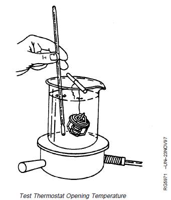
Test thermostat as follows:
CAUTION: DO NOT allow thermostat or
thermometer to rest against the side or bottom
of container when heating water. Either may
rupture if overheated.
1. Remove thermostats. (See procedure in Section 02,
Group 070.)
2. Suspend thermostat and a thermometer in a container
of water.
3. Stir the water as it heats. Observe opening action of
thermostat and compare temperatures with
specification given in chart below.
NOTE: Due to varying tolerances of different suppliers,
initial opening and full open temperatures may
vary slightly from specified temperatures.
THERMOSTAT TEST SPECIFICATIONS
Rating Initial Opening (Range) Full Open
(Nominal)
71°C (160°F) 69—72°C (156—162°F) 84°C (182°F)
77°C (170°F) 74—78°C (166—172°F) 89°C (192°F)
82°C (180°F) 80—84°C (175—182°F) 94°C (202°F)
89°C (192°F) 86—90°C (187—194°F) 101°C (214°F)
90°C (195°F) 89—93°C (192—199°F) 103°C (218°F)
92°C (197°F) 89—93°C (193—200°F) 105°C (221°F)
96°C (205°F) 94—97°C (201—207°F) 100°C (213°F)
99°C (210°F) 96—100°C (205—212°F) 111°C (232°F)
4. Remove thermostat and observe its closing action as it
cools. In ambient air the thermostat should close
completely. Closing action should be smooth and slow.
5. If any thermostat is defective on a multiple thermostat
engine, replace all thermostats.
John Deere約翰迪爾強鹿柴油機冷卻系統和散熱器壓力測試
CAUTION: Explosive released fluids from
pressurized cooling system can cause
serious burns.
Shut off engine. Only remove filler cap when
cool enough to touch with bare hands.
Slowly loosen cap to first stop to relieve
pressure before removing completely.
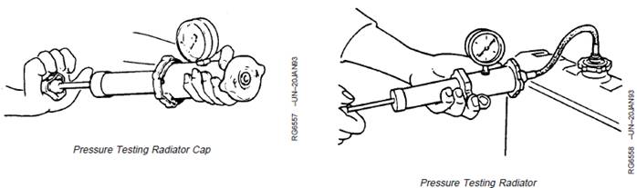
Test Radiator Cap:
1. Remove radiator cap and attach to D05104ST
Pressure Pump as shown.
2. Pressurize cap to the following specification1.
Two-Valve Head Engines and 4.5 L Four-Valve Head Engines—
Specification
Radiator Cap2—Holding
Pressure (10 Second Minimum
Hold) 70 kPa (0.7 bar) (10 psi)
Minimum
............................................................
6.8 L Four-Valve Head Engines—Specification
Radiator Cap3—Holding
Pressure (10 Second Minimum
Hold) 100 kPa (1.0 bar) (15 psi)
Minimum
..........................................................
Gauge should hold pressure for 10 seconds within the
normal range if cap is acceptable.
If gauge does not hold pressure, replace radiator cap.
3. Remove the cap from gauge, turn it 180°, and
retest cap. This will verify that the first
measurement was accurate.
Test Cooling System:
NOTE: Engine should be warmed up to test overall
cooling system.
1. Allow engine to cool, then carefully remove radiator
cap.
1Test pressures recommended are for all Deere OEM cooling
systems. On specific vehicle applications, test cooling system and
pressure cap according to the recommended pressure for that
vehicle.
26068HF275 Industrial OEM with VP44 pump use a radiator cap with
a pressure specification 100 kPa (1.0 bar) (15 psi) minimum.
36068HF475 for gen-set applications use a radiator cap with 70 kPa
(0.7 bar) (10 psi) minimum.
2. Fill radiator with coolant to the normal operating
level.
IMPORTANT: DO NOT apply excessive pressure to
cooling system. Doing so may
damage radiator and hoses.
3. Connect gauge and adapter to radiator filler neck.
Pressurize cooling system to specification listed for
radiator cap.1, using D05104ST Pressure Pump.
4. With pressure applied, check all cooling system
hose connections, radiator, and overall engine for
leaks.
If leakage is detected, correct as necessary and
pressure test system again.
If no leakage is detected, but the gauge indicated a
drop in pressure, coolant may be leaking internally
within the system or at the block-to-head gasket.
1Test pressures recommended are for all Deere OEM cooling
systems. On specific vehicle applications, test cooling system and
pressure cap according to the recommended pressure for that
vehicle.
John Deere約翰迪爾強鹿柴油機氣缸蓋墊片故障檢查
NOTE: Booklet DB1119—CYLINDER HEAD GASKET
FAILURES for 6466 and 6076 Engines can be
used as a guide for diagnosing head gasket
failures on POWERTECHâ 4.5 L and 6.8 L
Engines. However, use specifications provided in
this manual (CTM104).
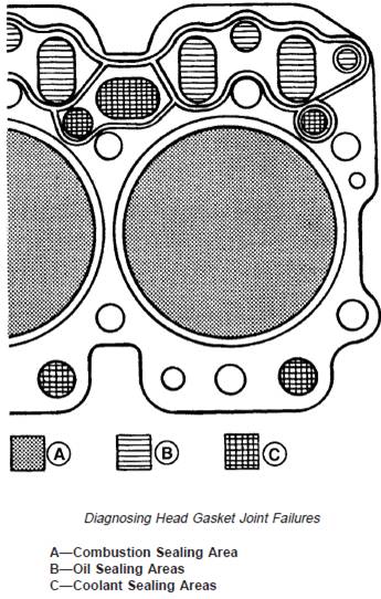
Head gasket failures generally fall into three categories:
· Combustion seal failures.
· Coolant seal failures.
· Oil seal failures.
Combustion seal failures occur when combustion gases
escape between cylinder head and head gasket
combustion flange, or between combustion flange and
cylinder liner. Leaking combustion gases may vent to an
adjacent cylinder, to a coolant or oil passage, or
externally.
Coolant or oil seal failures occur when oil or coolant
escapes between cylinder head and gasket body, or
between cylinder block and gasket body. The oil or
coolant may leak to an adjacent coolant or oil passage, or
externally. Since oil and coolant passages are primarily on
right-hand (camshaft) side of engine, fluid leaks are most
likely to occur in that area.
Follow these diagnostic procedures when a head gasket
joint failure occurs or is suspected.
1. Before starting or disassembling engine, conduct a
visual inspection of machine and note any of the
following:
· Oil or coolant in head gasket seam, or on adjacent
surfaces. Especially right rear corner of gasket joint.
· Displacement of gasket from normal position.
· Discoloration or soot from combustion gas leakage.
· Leaking radiator, overflow tank, or hoses.
· Leaking coolant from coolant pump weep hole.
· Damaged or incorrect radiator, fan, or shroud.
· Obstructed air flow or coolant flow.
· Worn or slipping belts.
· Damaged or incorrect pressure cap.
· Presence of oil in coolant.
· Low coolant levels or Improper coolant.
· Unusually high or low oil levels.
· Oil degradation, dilution, or contamination.
· Incorrectly specified injection pump.
· Indications of fuel or timing adjustments.
· Unburned fuel or coolant in exhaust system.
2. Obtain coolant and oil samples for further analysis.
3. Start and warm up engine if it can be safely operated.
Examine all potential leakage areas again as outlined
previously. Using appropriate test and measurement
equipment, check for the following:
· White smoke, excessive raw fuel, or moisture in
exhaust system.
· Rough, irregular exhaust sound, or misfiring.
· Air bubbles, gas trapped in radiator/overflow tank.
· Loss of coolant from overflow.
· Excessive cooling system pressure.
· Coolant overheating.
· Low coolant flow.
· Loss of cab heating (air lock).
4. Shut engine down. Recheck crankcase, radiator, and
overflow tank for any significant differences in fluid
levels, viscosity, or appearance.
5. Compare your observations from above steps with the
diagnostic charts earlier in this group. If diagnostic
evaluations provide conclusive evidence of combustion
gas, coolant, or oil leakage from head gasket joint, the
cylinder head must be removed for inspection and
repair of gasket joint components.
COMBUSTION SEAL LEAKAGE
Symptoms:
· Exhaust from head gasket crevice
· Air bubbles in radiator/overflow tank
· Coolant discharge from overflow tube
· Engine overheating
· Power loss
· Engine runs rough
· White exhaust smoke
· Loss of cab heat
· Gasket section dislodged, missing (blown)
· Coolant in cylinder
· Coolant in crankcase oil
· Low coolant level
Possible Causes:
· Insufficient liner standout
· Excessive liner standout differential between cylinders
· Low head bolt clamping loads
· Rough/damaged liner flange surface
· Cracked/deformed gasket combustion flange
· Out-of-flat/damaged/rough cylinder head surface
· Missing/mislocated gasket fire ring
· Block cracked in liner support area
· Excessive fuel delivery
· Advanced injection pump timing
· Hydraulic or mechanical disturbance of combustion seal
NOTE: Cracked cylinder head or liners may also allow
combustion gas leakage into coolant.
COOLANT SEAL LEAKAGE
Symptoms:
· Coolant discharge from head gasket crevice
· Coolant in crankcase oil
· Low coolant level
· High oil level
· Coolant discharge from crankcase vent
Possible Causes:
· Excessive liner standout
· Excessive liner standout differential between cylinders
· Low head bolt clamping loads
· Out-of-flat/damaged/rough block surface
· Out-of-flat/damaged/rough cylinder head surface
· Oil or coolant overheating
· Cracks/creases in gasket body surfaces
· Damage/voids in elastomer beading
OIL SEAL LEAKAGE
Symptoms:
· Oil discharge from head gasket crevice
· Oil in coolant
· Low crankcase oil level
· Reduced oil to rocker arms (noisy)
Possible Causes:
· Excessive liner standout
· Excessive liner standout differential between cylinders
· Low head bolt clamping loads
· Out-of-flat/damaged/rough block surface
· Out-of-flat/damaged/rough cylinder head surface
· Oil or coolant overheating
· Cracks/creases in gasket body surfaces
· Damage/voids in elastomer beading
· Damaged/missing O-ring seal at oil port to rocker arms
NOTE: Defective oil cooler may also allow oil leakage into
coolant.
免費熱線
400-100-8969???15088860848
400-100-8969???15088860848
機組銷售
0574-26871589? 15267810868
0574-26871589? 15267810868
配件銷售
0574-26886646? 15706865167
0574-26886646? 15706865167
維修熱線
0574-26871569 18658287286
0574-26871569 18658287286
手機端

微信公眾號